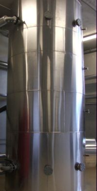
Buffer tanks, sometimes referred to as 'thermal stores' are crucial for the efficient operation of all biomass boilers where the system loading fluctuates rapidly, or the volume of water in the complete hydraulic system is relatively small. Using a suitably sized buffer vessel prevents rapid cycling of the boiler when the loading is below the minimum boiler output. Rapid cycling of the boiler causes a large increase in harmful emissions such as CO, dust, and NOx, greatly reduces boiler efficiency and increases electrical consumption of the unit. In addition, service and maintenance requirements will be increased as parts are stressed by rapid heating and cooling cycles. It should be noted that although most boilers claim to be able to turn down to 30% of nominal output, in the real world this is often not achievable due to differences in the fuel from the 'ideal' or test fuel. A suitably sized buffer tank should therefore be considered where the loading of the boiler drops below 50% of the nominal output - in other words unless the biomass component is purely base load, the system should include a buffer tank. In any case where the secondary system does not contain sufficient water for safe removal of residual heat from the biomass boiler irrespective of the loading conditions, the system must include a suitably sized buffer tank. The residual heat from a biomass unit varies greatly depending on the boiler design and the thermal mass of the combustion chamber. light weight, fast response boilers require only 10ltr/kW, while industrial wet wood units with very high thermal mass require 40ltr/kW
It should be noted at this point that the primary purpose of the buffer tank is to isolate the boiler from the effects of rapidly changing load conditions on the secondary side, by allowing a cool return supply to the boiler when none is forthcoming from the secondary system. In order to do this, the dominant control system must allow the buffer tank to operate over a temperature range, the bigger the range, the more effective the buffer tank becomes. Most biomass boilers feature an inbuilt buffer control system, which allows the commissioning engineer to set a turn on temperature for the boiler (usually based on the buffer tank top temperature) and a turn of temperature (based on the buffer tank bottom sensor). Ideally, the turn on temperature will be set as low as possible, and the turn of temperature as high as possible; this allows a greater amount of work to be done on the buffer vessel by the boiler, and therefore more effectively insulates the boiler from low load conditions on the secondary side. A common issue is that the master control system (BMS) is not sympathetic to the requirements of the biomass boiler and buffer tank, and enables additional heat sources before the buffer tank has cooled sufficiently to allow the biomass boiler to fire. This can result in peak load or backup boilers running against the load, back cycling heat to the buffer vessel, and preventing the biomass unit from firing at full output.
Using a buffer tank as a thermal store to overcome peaks in loading is possible, but can be detrimental to system performance. The buffer tank can be considered to be a large low loss header. A well understood principal of header system is that the primary side flow must be balanced with the secondary side flow to avoid mixing. For example, if a boiler is connected to a header and feeds in 80 degree water at a rate of 2l/s, and a single secondary circuit delivers at 4l/s, the flow temperature to the secondary circuit will be diluted by the cool secondary return. If a commissioning valve is adjusted to balance the two sides, the secondary circuit will flow at the correct temperature. The same logic applies to a buffer tank, therefore increasing the flow rate on the secondary side to provide for peak loads can cause a diluted flow temperature. A temperature differential between the top and bottom of the buffer tank allows full utilisation, therefore the flow rates on either side of the buffer vessel should be balanced wherever possible. If additional power is required for a short period, the secondary flow rate can be temporarily increased, but should not be set to run continually at a greater rate than the primary side.
